Hardwiring is the gold standard for professional lighting installations. While plug-and-play kits are convenient for temporary setups, they leave you with visible "wall wart" adapters and messy cables. By hardwiring, you integrate the lighting directly into your home's electrical system, allowing you to control your atmosphere with a standard wall switch or a high-end dimmer. This process involves connecting a dedicated LED driver to a 120V AC circuit, which then provides the precise low-voltage DC power required by the light strips.
A successful installation requires a balance of high-voltage electrical knowledge and low-voltage precision. The transition from the 120V "Line Voltage" in your walls to the 12V or 24V "Low Voltage" of the LEDs is handled by the driver. Doing this correctly ensures not only a clean aesthetic but also a system that operates coolly and lasts for its rated 50,000 hours.
Essential Components for a Hardwired System
Before stripping any wires, you must assemble the correct hardware. The most common mistake is mixing incompatible voltages or choosing a driver that cannot handle the load. A hardwired system is only as reliable as its weakest connection.
Component | Technical Requirement | Function |
|---|---|---|
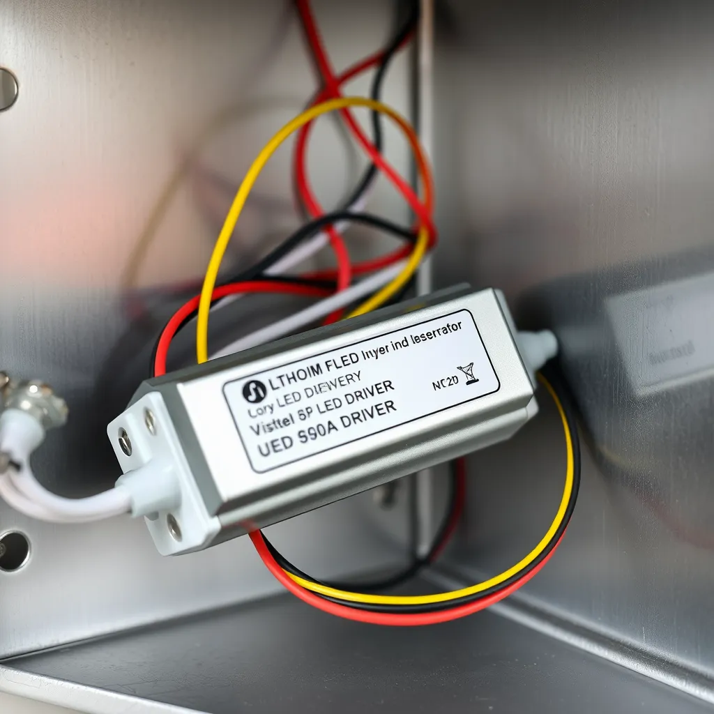
LED Driver | Constant Voltage (12V or 24V) | Converts 120V AC to DC power |
LED Strips | Must match Driver Voltage | The light source (tape/ribbon) |
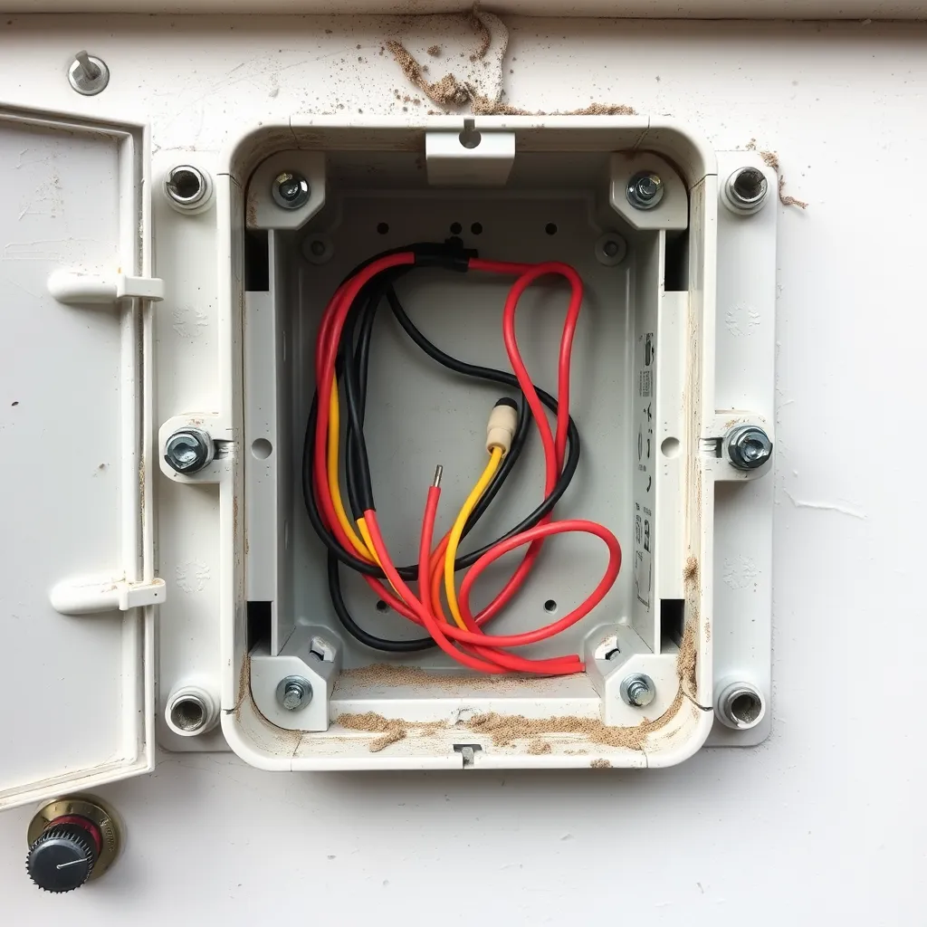
Junction Box | Metal or Plastic (UL Listed) | Encloses 120V connections for safety |
Primary Wire | 14/2 Romex (NM-B) | Carries 120V from switch to driver |
Secondary Wire | 18 AWG to 16 AWG CL2/3 | Carries low voltage from driver to strip |
Wall Dimmer | TRIAC, ELV, or 0-10V | Controls brightness via the driver |
Selecting the Correct Voltage: 12V vs. 24V
Most residential strips operate on either 12V or 24V DC. For hardwired installations, 24V systems are generally superior. Higher voltage means the system draws less current (amperage) for the same amount of power. This reduces "voltage drop"-the phenomenon where the LEDs at the end of a long run appear dimmer than those at the start. If your run exceeds 16 feet, 24V is the standard choice to maintain uniform brightness.
Calculating Driver Wattage (The 80% Rule)
LED drivers generate heat. To prevent premature failure, never load a driver to 100% of its rated capacity. Calculate your total wattage by multiplying the watts-per-foot of your strip by the total length. For example, if a strip uses 3 watts per foot and you are installing 15 feet, your total load is 45 watts. You should use a driver rated for at least 56 watts (45 / 0.80). Standardizing on a 60W or 75W driver in this scenario provides the necessary "headroom" for the electronics to breathe.
Detailed Step-by-Step Installation
Installing the system is a two-phase process: the high-voltage side (AC) and the low-voltage side (DC). Safety note: Always turn off the circuit breaker before beginning. Use a non-contact voltage tester to confirm the wires are cold.
Phase 1: The High-Voltage AC Side
The AC side involves bringing power from your house's electrical panel (or an existing junction box) to the LED driver. This wiring must follow the National Electrical Code (NEC). All 120V connections must occur inside a junction box. If your driver does not have a built-in enclosure, you must mount it inside a separate, ventilated metal box.
Route the Romex: Run 14/2 or 12/2 NM-B cable from your wall switch to the driver's location. Common locations for drivers include inside a kitchen cabinet, in a pantry, or in the attic.
Secure the Connections: Inside the junction box, connect the black (hot) wire from the switch to the black input wire of the driver. Connect the white (neutral) wires together. Attach the bare copper or green (ground) wire to the driver's ground screw or lead.
Strain Relief: Use cable clamps where the Romex enters the junction box. This prevents the wires from being pulled loose or chafing against the edge of the metal box.
Phase 2: The Low-Voltage DC Side
This is where the power leaves the driver and travels to the LEDs. Since this is low voltage (Class 2), you have more flexibility with how you run the wires, but quality still matters. 18 AWG (American Wire Gauge) is the standard for most residential runs under 20 feet.
Identify Polarity: DC power is directional. You must connect positive (+) to positive and negative (−) to negative. Usually, the red wire is positive and the black wire is negative.
Run the Secondary Wire: Run your low-voltage wire from the driver output to the start of your LED strip. You can hide this wire behind trim, inside cabinets, or through small holes in the drywall.
Attach to the Strip: Use high-quality solderless connectors or solder the wires directly to the copper pads on the strip. Solder is the most reliable method for a permanent installation, as mechanical connectors can occasionally loosen due to thermal expansion.
Mastering Dimming Compatibility
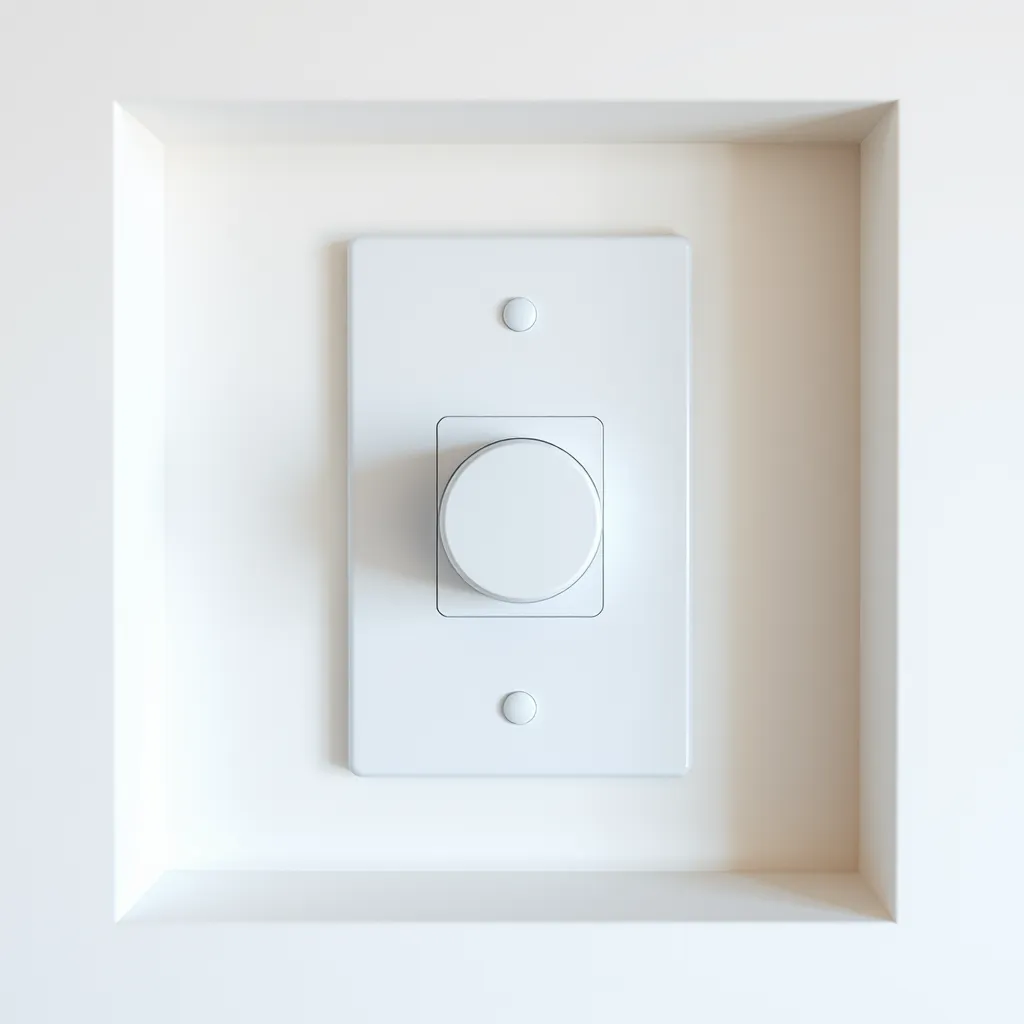
One of the primary reasons to hardwire is to use a high-quality wall dimmer. However, this is where most compatibility issues arise. Not all LED drivers "talk" to all dimmers. You must match the dimming technology of the driver to the switch on your wall.
TRIAC and ELV Dimming
Most residential dimmers use TRIAC (Forward Phase) or ELV (Reverse Phase) technology. These dimmers work by "chopping" the AC sine wave before it even reaches the driver. If you are using a standard Lutron or Leviton LED-rated dimmer, you must ensure your LED driver is explicitly labeled as "Phase Dimmable" or "Triac/ELV Compatible." ELV dimming is generally smoother and produces less "hum" or "buzz" than TRIAC.
0-10V Dimming
Used primarily in commercial spaces or high-end smart homes, 0-10V dimming uses a separate pair of low-voltage wires to send a signal to the driver telling it how much to dim. This provides the widest dimming range (down to 1%) without any flickering. This requires a 0-10V compatible driver and a specific 0-10V dimmer switch, which usually requires a 4-wire run (two for power, two for the signal).
Managing Voltage Drop for Long Runs
In a hardwired system, you might be tempted to run 50 feet of LED strip off a single driver. This leads to voltage drop. As electricity travels through the thin copper of the LED strip, it encounters resistance, which turns some of the energy into heat. By the time the electricity reaches the end of the strip, the voltage has dropped, resulting in dimmer lights.
How to Prevent Voltage Drop
Center-Feed the Power: Instead of connecting power to one end of a 30-foot run, connect the driver to the middle. This effectively cuts the distance the electricity has to travel in half.
Parallel Wiring: If you have multiple shelves, do not "daisy chain" them (connecting the end of one to the start of the next). Instead, run a separate "home run" wire from the driver to each individual strip.
Use 24V Systems: As mentioned, 24V is significantly more resistant to voltage drop than 12V.
Safety and Code Compliance
When you hardwire LED strip lights, the installation becomes a permanent part of the building's electrical system. This means it must adhere to the National Electrical Code (NEC). Failure to follow these rules can result in failed inspections or, worse, fire hazards.
Class 2 Power Sources
Most LED drivers are "Class 2" rated. This is a safety designation meaning the driver is designed to limit the risk of electric shock and fire. To maintain this rating, you must ensure your low-voltage wiring (the DC side) is kept separate from the high-voltage wiring (the AC side). Never run 120V wires and 12V/24V wires through the same conduit or junction box opening unless there is a physical barrier between them.
Accessibility Requirements
The NEC requires that all "transformers and power supplies" (drivers) remain accessible. You cannot bury an LED driver behind a finished drywall ceiling or wall. It must be in a location where it can be inspected or replaced without damaging the structure of the building. Standard locations include:
Inside a cabinet (with a removable cover or in plain sight).
In a drop ceiling or attic space.
Inside a recessed "media box" behind a TV.
Heat Dissipation
LEDs and their drivers are efficient, but they still produce heat. If a driver is placed in a tiny, unventilated box, it will overheat and shut down (or fail prematurely). Ensure there is at least a few inches of air space around the driver. If you are mounting the LED strips themselves in a high-power application (over 4 watts per foot), consider mounting them inside an aluminum channel. The aluminum acts as a heat sink, pulling heat away from the LED chips and extending their life.
Final Testing and Troubleshooting
Once the wiring is complete, it is time for the "smoke test." Turn the breaker back on and flip the switch. If the lights do not turn on, or if they behave strangely, check the following:
Flickering: This is usually a compatibility issue between the dimmer and the driver. Ensure both are rated for the same dimming protocol (e.g., both are ELV).
Partial Illumination: If only the first few feet of the strip light up, you likely have a poor connection at a solderless connector or a short circuit where the strip was cut.
Dimming at the End: This is the classic sign of voltage drop. Check your wire gauge or consider a 24V upgrade.
Delayed Start: Many high-quality drivers have a "soft start" feature that takes about half a second to turn on. This is normal and protects the LEDs from power surges.
Conclusion:
Hardwiring LED strip lights delivers a clean, professional, switch-controlled installation that plug-and-play kits simply can't match. Success hinges on getting the fundamentals right: select the correct voltage (24V for runs over 16 feet), size your driver using the 80% rule, and keep high-voltage AC wiring fully separated from low-voltage DC for safety and code compliance. Match your dimmer technology to your driver to avoid flickering and buzzing, and combat voltage drop with center-feeding, parallel wiring, or a 24V system. Always follow the NEC, keep drivers accessible, and ensure proper heat dissipation. Done correctly, your system will run cool and last its full 50,000-hour rating.
Frequently Asked Questions
Q1: Can I hide the LED driver inside a wall?
A: No. Per the National Electrical Code (NEC), all electrical drivers and transformers must remain accessible for maintenance and inspection. You can mount it in a cabinet, an attic, or a closet, but you cannot seal it behind drywall. If you must put it in a wall, use an access panel that can be opened without tools or by removing a few screws.
Q2: What gauge wire should I use for the low-voltage side?
A: For most residential runs under 20 feet, 18 AWG is sufficient. For longer runs (20-50 feet) or high-wattage strips, 16 AWG or even 14 AWG may be required to prevent voltage drop. Always use wire rated for "in-wall" use (CL2 or CL3 rating) if you are running the wire through wall cavities.
Q3: Can I use one driver for multiple separate LED strips?
A: Yes, as long as the total wattage of all strips combined does not exceed 80% of the driver's rated capacity. It is best to wire these strips in "parallel"-meaning each strip has its own set of wires going back to the driver-rather than connecting them end-to-end in a "series."
Q4: Do I need to ground the LED driver?
A: If the driver has a metal housing or a green/bare copper ground wire, yes, it must be grounded to your home's grounding system. This provides a safe path for electricity in the event of a fault and helps reduce electromagnetic interference (EMI) that can cause buzzing in audio equipment or flickering in the lights.