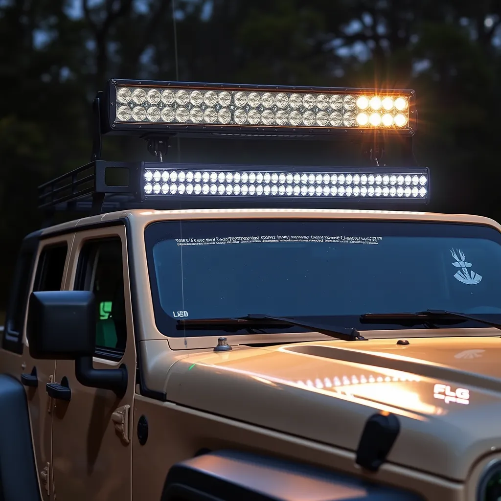
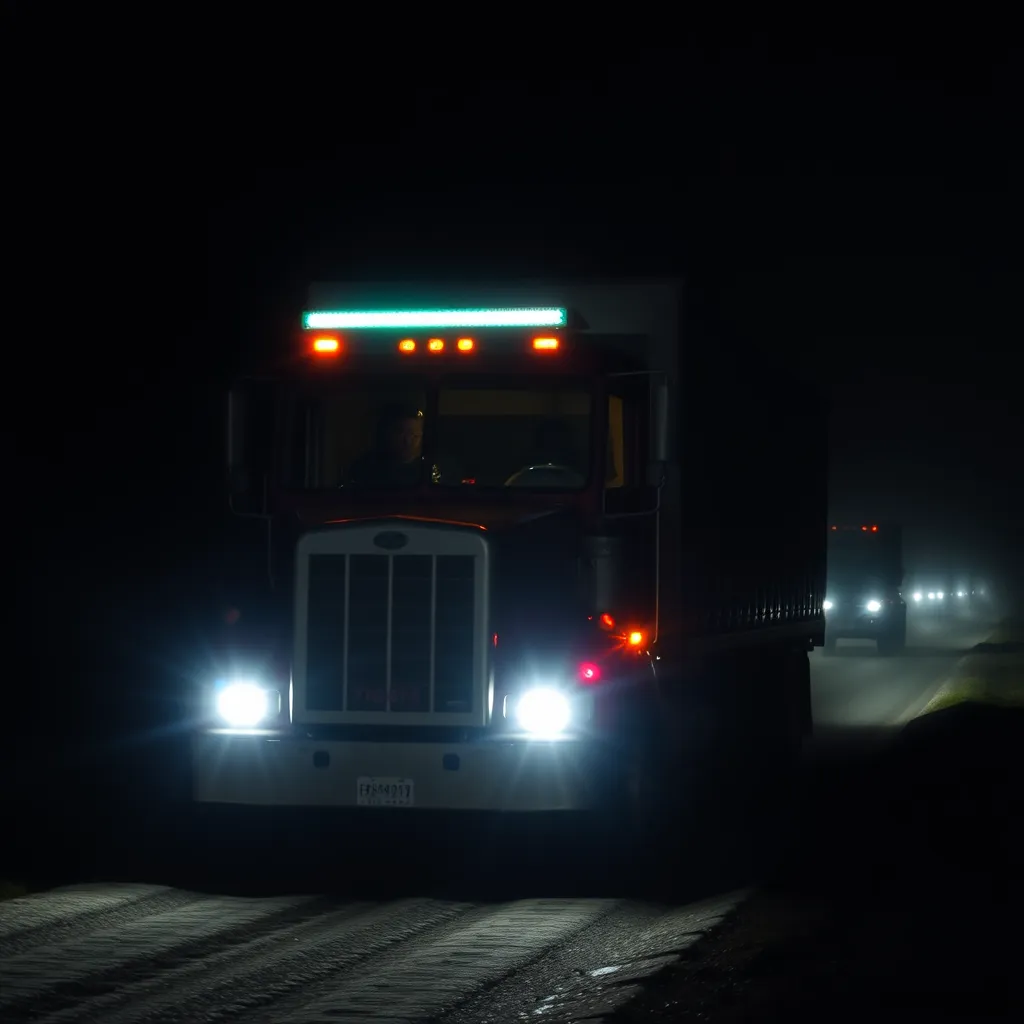
Adding high-intensity auxiliary lighting to a vehicle transforms the off-road driving experience, providing visibility that factory high beams cannot match. While the process is straightforward, the difference between a professional-grade setup and a hazardous one lies in the electrical execution and mounting stability. Understanding how to install a LED light bar correctly ensures that the equipment performs reliably under vibration, moisture, and high thermal loads without risking the vehicle's electrical integrity.
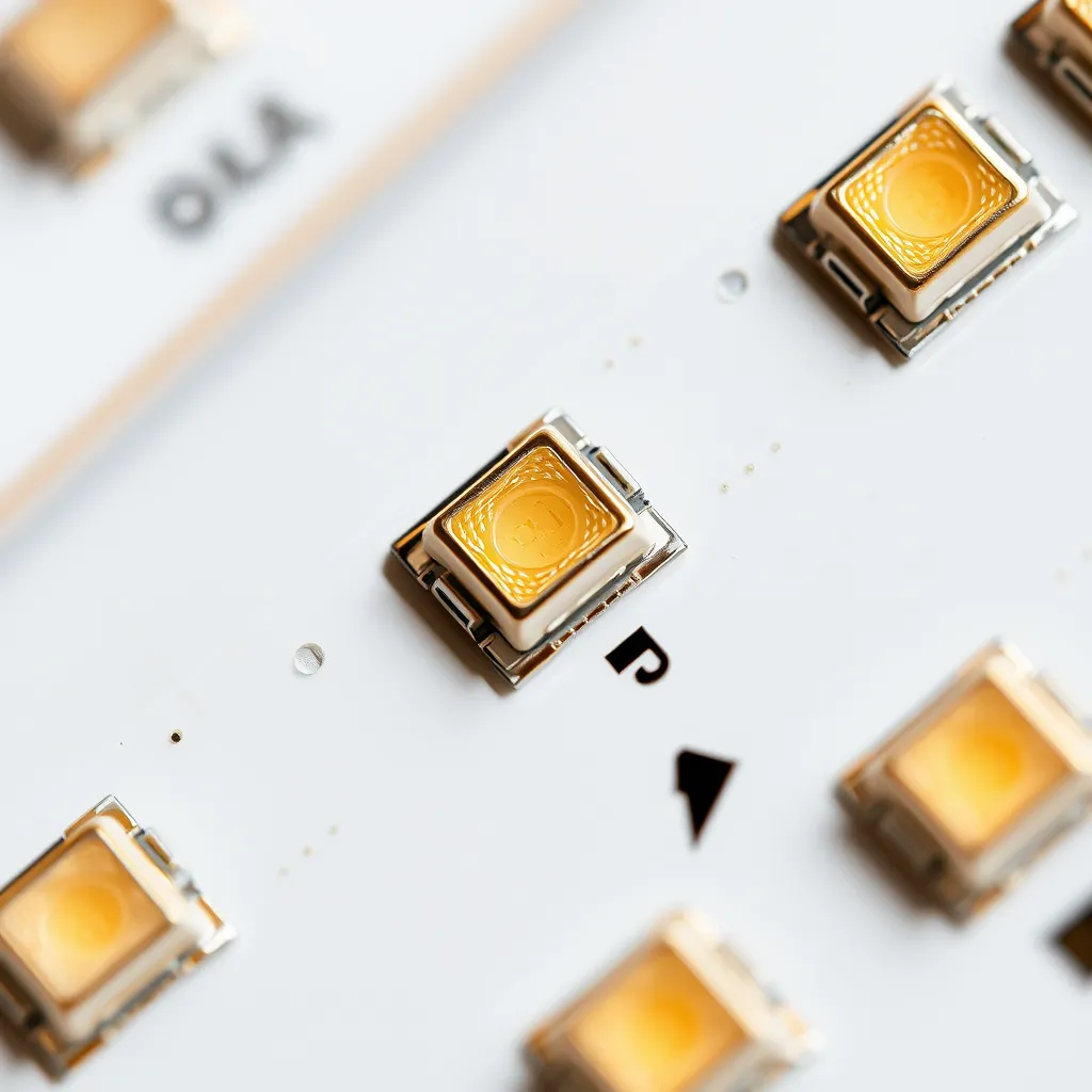
Most modern light bars utilize high-output SMD (Surface Mounted Device) LEDs that draw significant current. A 30-inch double-row bar can easily pull 15 to 25 amps. This current demand necessitates a dedicated circuit. Attempting to tap into existing headlight or fog light wiring will likely trigger the vehicle's Body Control Module (BCM) to shut down the circuit or, in older vehicles, blow fuses and overheat factory wiring. A standalone harness with a relay is the industry standard for a reason.
Essential Components and Specifications
Before beginning the installation, verify that the hardware matches the power requirements of the light. Using undersized wire or an underrated relay leads to voltage drop, which causes the LEDs to run dim and generate excess heat at the connection points.
Component | Specification/Requirement | Function |
|---|---|---|
Wiring Harness | 12 AWG or 14 AWG (Copper) | Carries high-current load from battery to light. |
Relay | 4-Pin or 5-Pin (40A rated) | Uses a low-current switch to trigger high-current power. |
Inline Fuse | 30A (or 125% of bar's max draw) | Protects the circuit from shorts and fire hazards. |
Switch | Rocker, Toggle, or Push-button | Provides user control from inside the cabin. |
Mounting Hardware | Stainless Steel (Grade 8) | Secures the bar against wind resistance and vibration. |
Choosing the Right Wire Gauge
Voltage drop is the enemy of performance. For a standard 12V system, a 3% voltage drop is the maximum acceptable limit. If the light bar is mounted on the roof (requiring roughly 15-20 feet of wire), the following gauges are recommended:
Light Bar Wattage | Recommended Wire Gauge (AWG) |
|---|---|
Up to 150 Watts | 14 AWG |
Exceeding 240 Watts | 12 AWG or 10 AWG |
Always prefer tinned copper marine-grade wire for off-road applications, as it resists the corrosion caused by road salt and moisture.
Selecting an Optimal Mounting Location
The placement of the light dictates the beam's effectiveness and the driver's comfort. There are four primary locations, each with distinct advantages and engineering challenges.
Roof and Upper Windshield Mounts
Mounting at the roofline provides the greatest distance for the beam and illuminates "dips" in the terrain that lower lights might miss. However, this position often causes significant "hood glare," where light reflects off the vehicle's hood back into the driver's eyes. To mitigate this, mount the bar slightly further back on the roof or use a matte black hood wrap. Additionally, roof-mounted bars are prone to wind whistling; installing rubber harmonic dampeners in the rear cooling fins can eliminate this high-pitched noise.
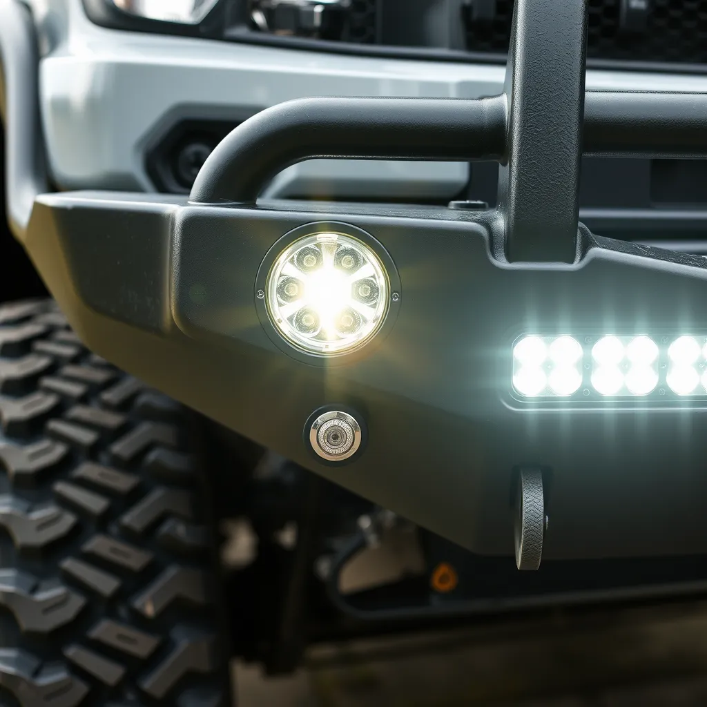
Bumper and Grille Integration
Bumper mounting is the most common choice for "driving" or "combo" beam patterns. It places the light source closer to the ground, which is superior for cutting through dust or light fog. Internal grille mounts offer a "stealth" look and protect the light bar from trail obstacles like low-hanging branches. The trade-off is a slight reduction in total lumen output due to the grille mesh obstructing the periphery of the beam.
A-Pillar (Ditch Light) Positions
While usually reserved for smaller pods, some brackets allow for small bars at the base of the A-pillar. These are typically aimed outward at a 45-degree angle to illuminate the sides of the trail, helping the driver spot animals or navigate tight turns where the headlights are pointed straight ahead.
Mechanical Installation and Alignment
Once the location is chosen, the mechanical attachment must be robust. A 50-inch light bar acts like a sail at 70 mph, exerting hundreds of pounds of force on the brackets. Use the following steps for a secure mount:
Template and Marking: Hold the light bar with the brackets attached to the mounting surface. Mark the hole centers with a center punch to prevent the drill bit from wandering.
Drilling: Use a cobalt drill bit for stainless steel or heavy-duty bumpers. If drilling into the roof, use a drill stop to prevent the bit from plunging into the headliner.
Corrosion Protection: Apply a zinc-rich primer or clear silicone to any bare metal exposed by drilling. For roof mounts, use rubber well-nuts or a generous amount of RTV silicone sealant to ensure a watertight seal.
Fastening: Use nylon-insert lock nuts (Nyloc) or blue thread-locking compound. Standard washers will eventually vibrate loose on corrugated dirt roads.
Proper aiming is often overlooked. To aim the bar, park the vehicle on a level surface facing a wall 25 feet away. The "hot spot" of the beam should be roughly 2-4 inches below the horizontal centerline of the light bar itself. This ensures the light reaches far down the trail without wasting energy illuminating the sky or the foreground immediately in front of the tires.
The Electrical Circuit: Relay Logic Explained
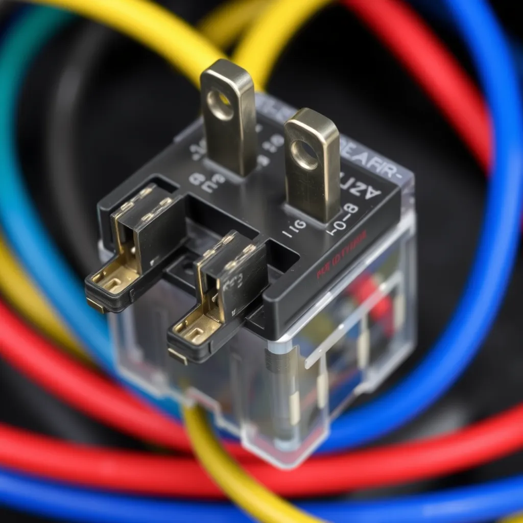
The core of a safe installation is the relay. A relay is an electromagnetic switch. When you flip the small switch in your cabin, it sends a tiny amount of current (about 0.2 amps) to a coil inside the relay. This creates a magnetic field that pulls a heavy-duty contact closed, allowing the high-current power to flow directly from the battery to the light bar. This prevents high amperage from ever entering the passenger cabin.
Standard Relay Pinout (Bosch Style)
Relay Pin | Connection Point |
|---|---|
Pin 30 | High-current input (Battery positive terminal via fused lead) |
Pin 87 | High-current output (Light bar positive wire) |
Pin 85 | Relay coil ground (Chassis ground or battery negative) |
Pin 86 | Relay coil trigger (Connect to cabin switch) |
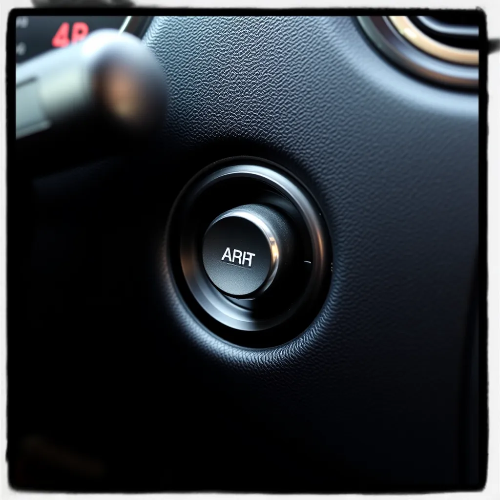
Switch Wiring Options
You have two choices for powering the cabin switch (Pin 86):
Constant 12V Source: Allows the light bar to turn on even when the vehicle is off-useful for camping but risky if you forget to turn it off.
Switched Source: Connecting to a source like the cigarette lighter or an ignition fuse ensures the light bar only functions when the key is in the accessory or run position.
Routing Wires and Firewall Access
Managing the "spaghetti" of wires is what separates a DIY job from a professional one. Route the main harness along the inner fender well, following factory wire looms wherever possible. Use UV-rated zip ties every 6 to 10 inches to prevent the wires from sagging or rubbing against hot engine components.
To get the switch wires into the cabin, look for a factory rubber grommet in the firewall. These are often located near the steering column or the brake booster. Use a plastic "fish tape" or a straightened coat hanger to gently pull the wires through. Never run wires through the door jamb or around the edge of the hood without a grommet, as the sharp metal edges will eventually cut through the insulation and cause a short circuit.
Final Connections and Environmental Sealing
The most common failure point in auxiliary lighting is the ground connection. A "floating ground" (a loose or painted connection) causes flickering and can damage the LED drivers. Grind away a small patch of paint on the chassis to expose bare metal, attach your ring terminal, and then coat the connection with battery terminal protector or fluid film to prevent rust.
For the external connections at the light bar itself, use Deutsch (DT) connectors if they aren't already provided. These are waterproof, vibration-resistant plugs used in heavy machinery. If you must use crimp connectors, always use the heat-shrink variety. After crimping, use a heat gun to shrink the tubing until the internal adhesive oozes out, creating a permanent, airtight seal against the elements.
Testing and Troubleshooting
Before finalizing the trim and panels, perform a functional test. If the light does not illuminate, check these three areas in order:
The Fuse: Check the inline fuse near the battery. If it is blown, there is a short in your high-current path (Pin 30 or 87).
The Relay Click: Have someone flip the switch while you stand near the relay. You should hear a distinct "click." If you don't hear it, the relay isn't receiving the trigger signal (check Pin 86) or the coil isn't grounded (check Pin 85).
Ground Integrity: Use a multimeter to check continuity between the light bar's negative wire and the battery's negative terminal. Resistance should be near zero ohms.
Maintenance and Long-Term Care
LED light bars are generally low-maintenance, but the harsh environments of off-roading require occasional attention. Periodically check the mounting bolts; the constant vibration of washboard roads can loosen even the best hardware. If you notice condensation inside the lens, the breather valve may be clogged or the seal may have failed. Many high-quality bars feature a "Gore-Tex" style breather that allows pressure to equalize without letting moisture in; ensure this is clean and unobstructed.
Clean the polycarbonate lens with mild soap and water only. Avoid using harsh chemicals or abrasive sponges, as these can scratch the UV coating, leading to yellowing or cloudiness over time. A coat of high-quality automotive wax on the lens can help shed mud and water during your next outing.
Conclusion:
Installing a LED light bar is more than just bolting hardware onto a vehicle-it's an exercise in electrical discipline and mechanical precision. By using the correct wire gauge, a properly rated relay, and weather-sealed connections, you protect both your investment and your vehicle's factory wiring. Thoughtful mounting placement and accurate aiming transform raw lumens into usable trail visibility, while routine inspections of bolts, grounds, and seals keep performance consistent over the long haul. Whether you're navigating rocky backcountry or dusty desert tracks, a well-installed light bar delivers the confidence and clarity that factory headlights simply cannot match on demanding off-road adventures.
Frequently Asked Questions
Q1: Is it legal to drive with a light bar on the road?
A: In almost all jurisdictions, LED light bars are classified for "off-road use only." They do not meet DOT (Department of Transportation) or SAE beam pattern requirements for on-road use because they lack a sharp "cut-off" line, meaning they blind oncoming drivers regardless of how they are aimed. Many states require light bars to be covered with an opaque shield while driving on public highways. Always check local statutes to avoid equipment violations.
Q2: Can I connect the light bar directly to my high beam circuit?
A: You can use the high beam wire as a "trigger" for your relay (connecting it to Pin 86). This allows the light bar to turn on automatically whenever you activate your high beams. However, you should still include a secondary switch in the cabin so you can disable this feature when you only want standard high beams. Never power the light bar directly from the high beam wire, as it will likely overload the factory circuit.
Q3: Why does my light bar make a whistling sound at high speeds?
A: Whistling is caused by air passing over the cooling fins on the back of the light bar, creating a "flute" effect. This is most common with roof-mounted bars. You can solve this by disrupting the airflow. Commercial "anti-whistle" rubber inserts can be pressed into the fins, or you can simply run a bead of silicone across the fins or wrap a small section of door edge guard molding around the bottom fin to break up the wind pattern.