Testing a light-emitting diode (LED) is a fundamental skill for electronics hobbyists, DIYers, and homeowners looking to repair fixtures rather than replace them. Unlike incandescent bulbs, which fail when a physical filament breaks, these components are semiconductors. They fail due to heat degradation, electrical surges, or manufacturing defects in the junction. Understanding how to diagnose these issues requires a basic grasp of polarity and forward voltage.
Because these components only allow electricity to flow in one direction, a standard continuity test often fails to provide a clear answer. You must verify the integrity of the diode junction itself. This process varies slightly depending on whether you are working with individual chips, flexible strips, or fully enclosed household bulbs.
The Science of the Diode Junction
To effectively determine if a component is functional, you must understand the "Forward Voltage" ($V_f$). Every diode has a specific threshold of voltage required to "push" electrons across the semiconductor junction. If the testing device provides less than this voltage, the light remains off, even if it is perfectly healthy.
Red LEDs typically require the least amount of energy, while blue and white versions require the most. This is due to the bandgap of the materials used (such as Gallium Arsenide or Gallium Nitride). If a testing method does not account for these specific voltage requirements, it may yield a false negative.
LED Color | Typical Forward Voltage ($V_f$) | Typical Test Current |
|---|---|---|
Red | 1.8V - 2.1V | 20mA |
Orange / Yellow | 2.0V - 2.2V | 20mA |
Green (Traditional) | 2.0V - 2.5V | 20mA |
Blue / Royal Blue | 3.0V - 3.4V | 20mA |
Pure White / Warm White | 3.0V - 3.5V | 20mA |
Ultraviolet (UV) | 3.2V - 3.8V | 20mA |
Primary Diagnostics with a Multimeter
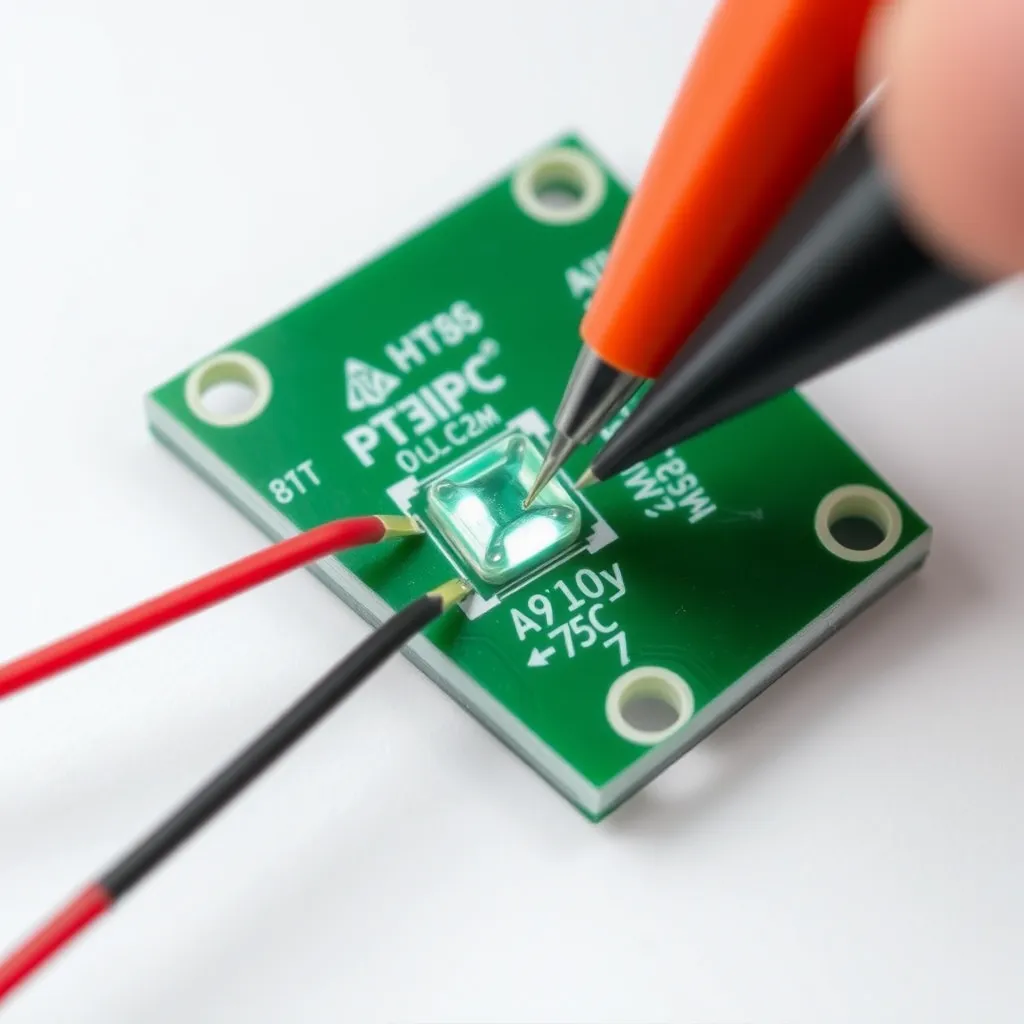
The most reliable way to test LED lights is using a digital multimeter (DMM) set to Diode Mode. This mode is specifically designed to send a small current through a component and measure the resulting voltage drop.
Step-by-Step Multimeter Procedure
Select Diode Mode: Turn the multimeter dial to the symbol that looks like an arrow pointing at a vertical line. If your meter shares this setting with continuity (the "beep" mode), press the "Select" or "Mode" button until the diode symbol appears on the LCD.
Identify Polarity: The longer leg of a new LED is the Anode (positive), and the shorter leg is the Cathode (negative). If the legs have been trimmed, look for a flat spot on the plastic casing; this marks the cathode side.
Apply Probes: Touch the red (positive) probe to the anode and the black (negative) probe to the cathode.
Observe the Display: A healthy component will show a numerical value (the forward voltage drop) on the screen. Most multimeters will also provide enough current to make the LED glow dimly during this test.
Reverse the Probes: As a secondary check, swap the probes. The meter should read "OL" (Open Loop) or "1". This confirms the diode is blocking current in the reverse direction as intended.
If the meter shows "OL" in both directions, the internal bond wire is broken (an open circuit). If the meter shows "0.00" or a very low number in both directions, the semiconductor junction has fused (a short circuit). In both cases, the component is defective.
Using a Coin Cell Battery for Quick Checks
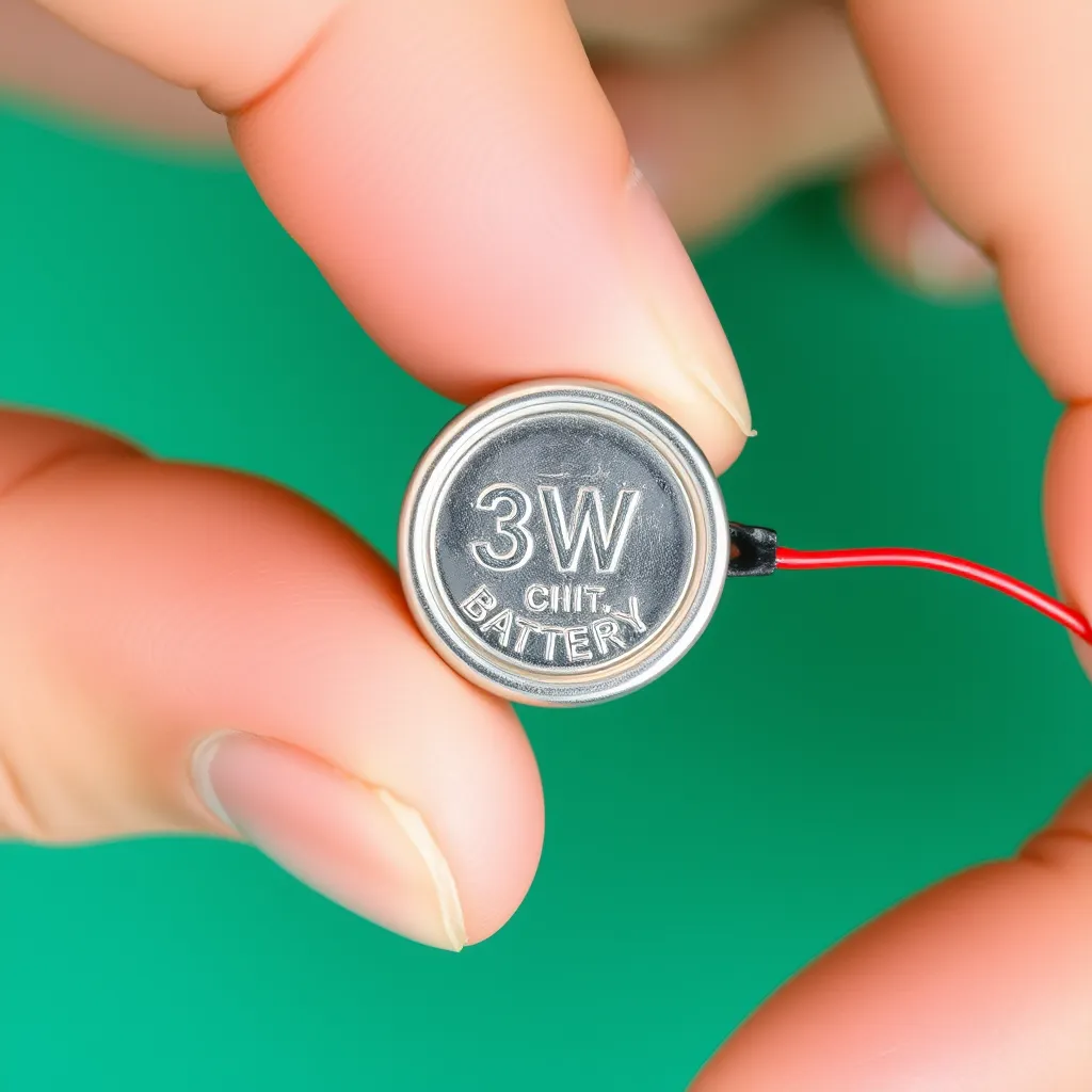
When a multimeter is unavailable, a 3V lithium coin cell battery (CR2032 or similar) is an effective diagnostic tool for individual 3mm or 5mm components. These batteries are ideal because their internal resistance naturally limits the current, preventing the LED from burning out instantly.
To perform this test, slide the LED legs over the battery so that the longer leg touches the side marked with a "+" and the shorter leg touches the textured negative side. A functional light will illuminate immediately.
Caution: Never use a 9V battery or a high-current power supply for this test without a resistor. A 9V battery provides enough pressure to force too much current through the junction, causing the LED to pop or smell like burning plastic within milliseconds. To use a 9V battery safely, you must place a 330-ohm to 1k-ohm resistor in series with one of the leads.
Analyzing Flexible Strip Lights
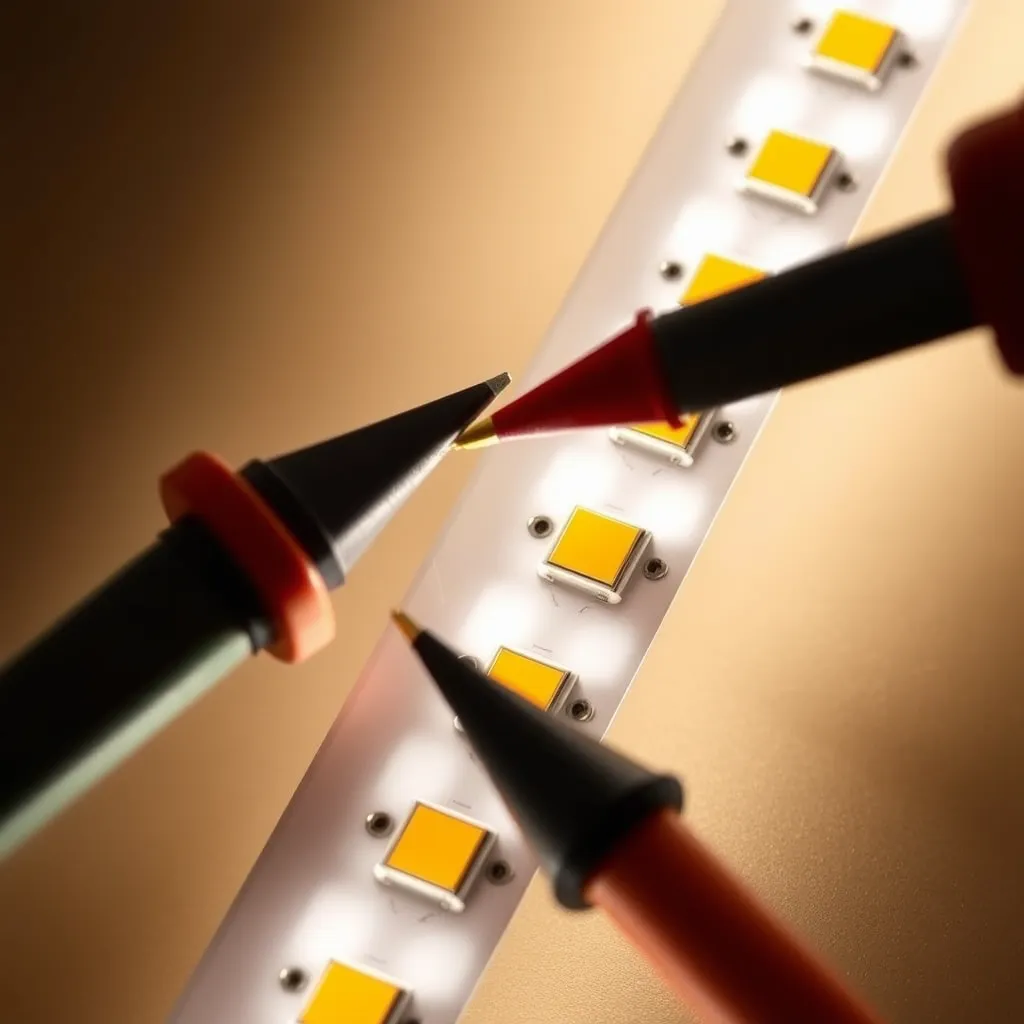
Flexible tape lights are more complex because they consist of groups of LEDs wired in series, with those groups then wired in parallel. If a single segment of three or six lights fails while the rest of the strip remains lit, the issue is localized to that specific "cut segment."
Locating the Failure Point
Set your multimeter to DC Voltage mode (usually 20V or 200V range). Connect the strip to its intended power supply. Carefully touch the probes to the copper solder pads at the beginning of the dark segment. If the meter reads 12V or 24V but the lights are off, the break is within that segment-likely a cracked solder joint or a failed resistor. If the meter reads 0V, the break is earlier in the strip, meaning power is not reaching that section at all.
For RGB strips where one color is missing, the problem is often a "cold" solder joint at the connector. These strips use a common anode (positive) and three separate cathodes for Red, Green, and Blue. If the blue channel is out across the whole strip, check the "B" wire connection at the controller or the first solder point on the tape.
Evaluating Household LED Bulbs
Testing a standard A19 or BR30 household bulb is different because the LEDs are hidden behind a diffuser and powered by an internal driver circuit. These drivers convert 120V/230V AC into low-voltage DC.
When an LED bulb fails to turn on, the culprit is usually the driver, not the LED chips themselves. Electrolytic capacitors inside the driver are prone to heat failure. To test the bulb:
The Socket Test: Always verify the fixture first. Move the bulb to a known working lamp. If it works there, the issue is the original socket's tab (which may need to be bent up slightly) or the wall switch.
The Dimmer Check: If a bulb flickers or buzzes, verify it is labeled as "dimmable." Using non-dimmable LEDs on a phase-cut dimmer circuit causes rapid cycling that can destroy the driver.
Visual Inspection: If you can safely remove the plastic diffuser, look at the "COB" (Chip on Board) array. A failed LED often has a tiny black dot in the center, indicating a burnt-out junction. Because these are often wired in series, one "black dot" chip will cause the entire bulb to stay dark.
Advanced Diagnosis: The LED Driver
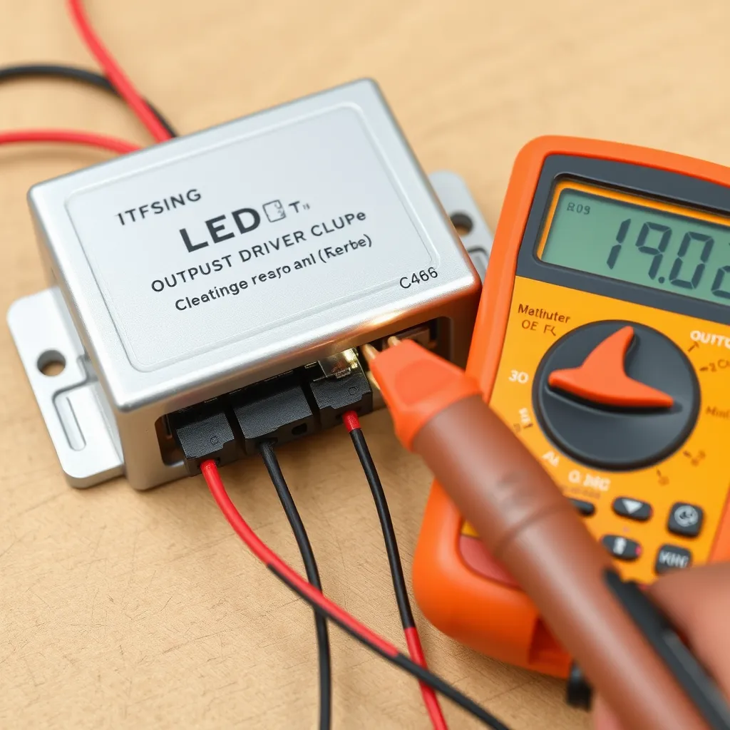
If you are working with architectural lighting or large panels, you may need to test the power supply (driver). Drivers are categorized as either Constant Voltage (CV) or Constant Current (CC).
A 12V strip driver is a Constant Voltage source. To test it, disconnect the lights and measure the output wires with a multimeter set to DC Voltage. It should read exactly 12V (or slightly higher, around 12.2V).
A dedicated COB driver (like those in recessed "pot" lights) is usually Constant Current. These are harder to test because they require a load to function correctly. If you measure a CC driver without a load, the voltage may "float" or pulse. The best way to test these is to swap the driver with an identical unit from a working fixture.
Common Mistakes to Avoid
Testing in Resistance Mode: Using the Ohms ($\Omega$) setting rarely works. Most multimeters do not output enough voltage in resistance mode to overcome the forward voltage of the diode, resulting in an "open" reading even on a good light.
Ignoring Heat Sinks: High-power LEDs (3W and above) generate intense heat. If you are testing these by applying power directly, do not leave them on for more than 1-2 seconds unless they are mounted to a heat sink. They can reach destructive temperatures almost instantly.
Assuming All Strips are 12V: Many modern high-density strips are 24V. Applying 12V to a 24V strip will result in extremely dim or no light, leading you to believe the strip is broken when it is simply underpowered.
Conclusion:
Mastering these testing techniques ensures that you can identify whether a failure lies within the LED chip itself or the supporting circuitry. In many cases, a non-functional fixture is simply the result of a loose connection or a failed driver rather than a burnt-out diode. By isolating the problem systematically, you save time and reduce electronic waste by repairing only the components that are truly broken.
As LED technology continues to evolve, integrated smart features and complex driver designs may require more sophisticated diagnostic tools. However, the fundamental principles of polarity and forward voltage remain the same. Keeping a reliable multimeter and a few spare batteries in your toolkit will allow you to maintain your home lighting systems with confidence and precision for years to come.
Frequently Asked Questions
Q1: Can I test an LED while it is still soldered to a circuit board?
A: You can often get a basic reading using diode mode in-circuit, but other components like resistors or capacitors in parallel can bypass the meter's current, giving you a false reading. For an accurate diagnosis, it is best to desolder at least one leg (the anode) to isolate the component from the rest of the board.
Q2: Why does my LED glow when I touch the multimeter probes to it?
A: This is normal and a sign of a healthy component. In diode mode, the multimeter sends a small current (usually around 1mA to 2mA) through the probes. While this is much lower than the standard 20mA operating current, it is enough to excite the electrons in the semiconductor and produce a visible, faint glow.
Q3: What does a black spot on an LED chip mean?
A: A black spot usually indicates a localized "burn-out" where the semiconductor material has overheated and carbonized. This is a definitive sign of failure. In series-wired products like LED bulbs or Christmas lights, this single failure acts like a blown fuse, preventing the entire string or array from lighting up.
Q4: My multimeter doesn't have a diode mode. Can I still test LEDs?
A: If your meter lacks diode mode, you can use the Continuity setting as a backup, though it is less reliable. Some high-end meters have enough "compliance voltage" in continuity mode to light an LED, but many do not. If both fail, use the 3V coin cell battery method described above for a definitive visual test.